How to tune a Coaxial Filter
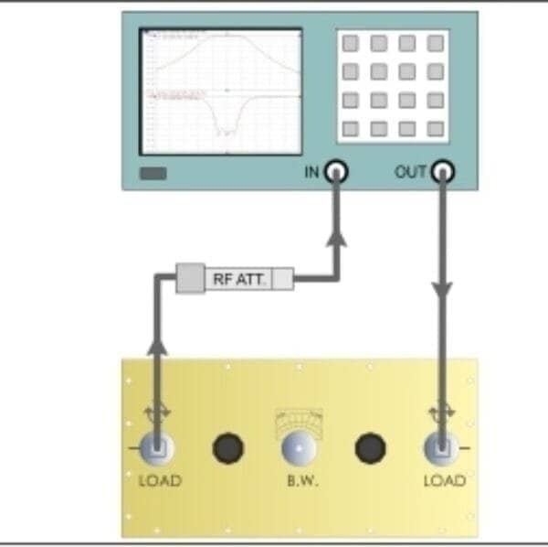
In Fig is shown the connection between Network Analyzer and a Coaxial Filter: with this kind of connection you can measure the Return Loss and the Standing Wave Ratio of the cavity. The frequency Span of the test instrument will be from 5 to 10 MHz. Moving them symmetrically, the return loss change and the frequency will move slowly. The B.W. command allows to set the selectivity of the filter. With the B.W. command extremely open the selectivity will be minimum as the attenuation loss. With the B.W. command closed the selectivity will be maximum as the attenuation loss.
The Coaxial Filter is tuned by move up/down the 2 knobs named “TUNE” for the frequency and rotate the in/out connectors named “LOAD” for the correct Return Loss.
Usually it is better to tune the coaxial filter trying to obtain the best Return Loss inside the wanted band, this is the best way to obtain also a low attenuation between the input and the output port of the filter. If a measure like this is made only using the SWR meter of a transmitter it could be possible to make a big mistake, because the operator could think he optimized the transmission while instead the transmitter is working at the left or right side of the band, so during the modulation it could happen that the SWR increases.
